STOMP User Guide
STOMP User Guide
Coupled Well Card Options
The coupled well model for STOMP-CO2 allows the specification of both injection and production type wells. Injection wells are mass type and production wells can be either volumetric or mass type wells.
- Well Model Description
- Well Trajectories
- CO2 Injection Wells
- Aqueous Injection Wells
- Production Wells (Volumetric or Mass)
- Alternating State Wells (WAG)
Well Model Description
Wells are the primary engineered component of geologic sequestration systems with deep subsurface reservoirs. Wells provide a conduit for injecting greenhouse gases and producing reservoirs fluids, such as brines, natural gas, and crude oil, depending on the target reservoir. Well trajectories, well pressures, and fluid flow rates are parameters over which well engineers and operators have control during the geologic sequestration process. Current drilling practices provided well engineers flexibility in designing well trajectories and controlling screened intervals. Injection pressures and fluids can be used to purposely fracture the reservoir formation or to purposely prevent fracturing. Numerical simulation of geologic sequestration processes involves the solution of multifluid transport equations within heterogeneous geologic media. These equations that mathematically describe the flow of fluid through the reservoir formation are nonlinear in form, requiring linearization techniques to resolve. In actual geologic settings, fluid exchange between a well and reservoir is a function of local pressure gradients, fluid saturations, and formation characteristics. In numerical simulators, fluid exchange between a well and reservoir can be specified using a spectrum of approaches that vary from totally ignoring the reservoir conditions to fully considering reservoir conditions and well processes. Well models are a numerical simulation approach that account for local conditions and gradients in the exchange of fluids between the well and reservoir. As with the mathematical equations that describe fluid flow in the reservoir, variation in fluid properties with temperature and pressure yield nonlinearities in the mathematical equations that describe fluid flow within the well. To numerically simulate the fluid exchange between a well and reservoir, the two systems of nonlinear multifluid flow equations must be resolved. The spectrum of numerical approaches for resolving these equations varies from zero coupling to full coupling. The well model in STOMP-CO2 is a fully coupled solution approach that allows for a flexible well trajectory and screened intervals within a structured hexahedral computational grid (see well trajectory tab). In this scheme, the nonlinear well equations have been fully integrated into the Jacobian matrix for the reservoir conservation equations, minimizing the matrix bandwidth.
Well Model
Mass flow between the well node and field node depends on the pressure differential, fluid viscosity, and the well index.
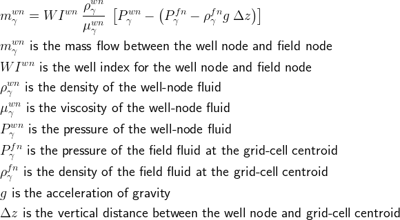
Mass flow for the well is the integrated mass flow over the well nodes.

The classical approach to the well problem is the Peaceman model (Peaceman, 1977; Peaceman, 1982; and Peaceman, 1987) for the well index, which is based on single-phase steady-state radial flow from a vertical well section into a grid cell. The radius of the grid cell is defined as the radial position at which the grid-cell pressure is equal to the pressure obtained from the analytical radial solution.
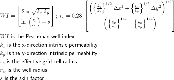
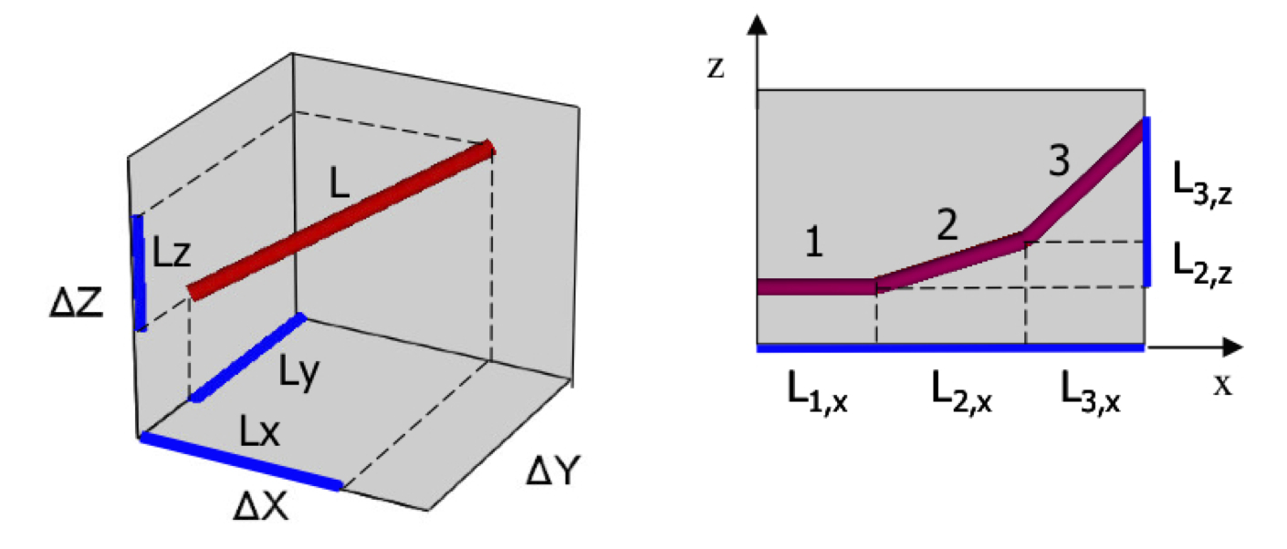
A projection well index replaces the classical Peaceman well index to account for non-vertically oriented well intervals. Images from Shu, J. 2005. Comparisons of Various Techniques for Computing Well Index, Master of Science Thesis, Stanford University, Stanford, California.
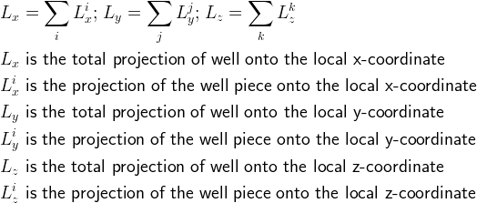
Multiple well nodes within a single grid cell are combined into a single effective well interval by summing the well-node projections onto the local grid-cell coordinates
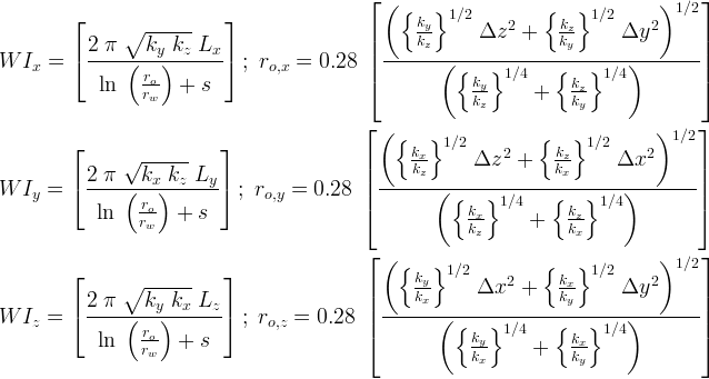
Well-node projections are combined into a single well index, using the projection model developed by Shu, 2005; where, the directional equivalent radii are defined in terms of directional intrinsic permeability and grid cell dimensions.

Peaceman, DW. 1977. "Interpretation of Well-Block Pressures in Numerical Reservoir Simulation." Paper SPE-6893, presented at the SPE-AIME 52nd Annual Fall Technical Conference and Exhibition, Denver, Oct. 9-12, 1977.
Peaceman, DW. 1982. "Interpretation of Well-Block Pressures in Numerical Reservoir Simulation With Nonsquare Grid Blocks and Anisotropic Permeability." Paper SPE-10528, presented at the 1982 SPE Symposium on Reservoir Simulation, New Orleans, Jan. 31-Feb. 3, 1982.
Peaceman, D Off-Center and Multiple Wells Within a Wellblock." Paper SPE-16976, presented at the 1987 SPE Annual Technical Conference and Exhibition, Dallas, Sept. 27-30, 1987.
Shu, J. 2005. Comparison of Various Techniques for Computing Well Index, Master of Science Thesis, Stanford University, Stanford, California.Well Trajectories
Well trajectories are specified using straight-line segments in the natural drilling direction. The individual well sections can be screened or unscreened and have associated radii and skin factors. The trajectories of well sections are specified via a starting (i.e., first transition point) x, y, z point in the global coordinate system and an ending (i.e., second transition point) x, y, z point in the global coordinate system. Well transition points are not permitted that coincide with a grid-cell surface. A specified well trajectory can begin outside the model domain, however, the only portions of the well trajectories that are active are those within a grid-cell volume. The translation of well trajectories into well nodes and connections between well nodes and field nodes will require computational time at the start of the simulation. For large domains and large well counts this initialization stage will require some time to complete, but is only required at the start of the simulation.
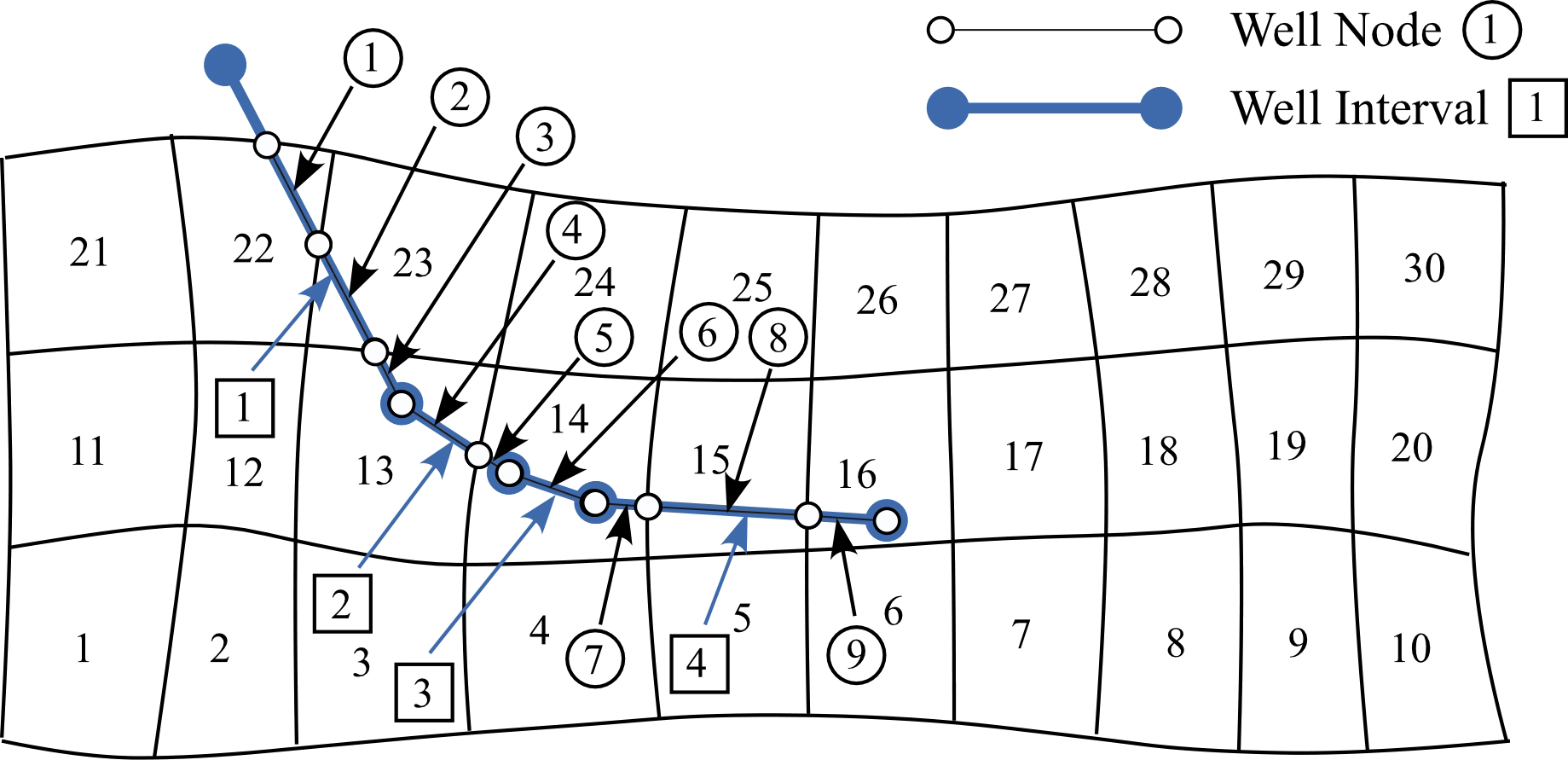
Well trajectories are declared by specifying linear sections of screened intervals (i.e., well intervals). Linear sections are defined by specifying the three-dimensional coordinate locations (i.e., x, y, z) of the two end points. Well trajectories are discretized into well nodes according to the computational grid and well intervals.
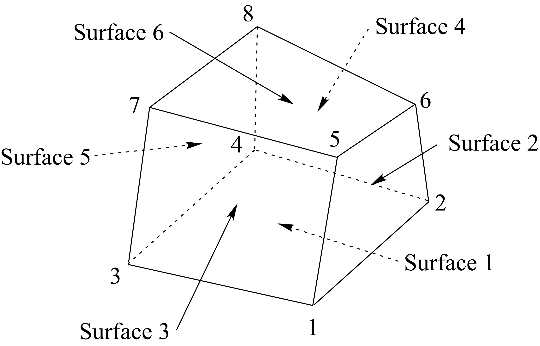
Well interval end points are located within a hexahedron grid cell by checking the sign of the dot product of the vector between the end point and surface centroid with the cross product of the vector between the end point and two vertices. Each hexahedron surface comprises four triangular planar surfaces. If the sign of the dot product is the same for all 24 grid cell surfaces, then the end point is within the grid cell, otherwise the end point is outside the grid cell.
CO2 Injection Wells
The CO2 injection well is used to specify the injection of a CO2 at a particular mass rate. CO2 will be injected from the well into the field grid cells across the screened interval. The distribution of CO2 crossing the well surface depends on the resistance to flow as defined by the local well index, fluid mobility, and driving force across the well surface. The CO2 injection rate is additionally bound by a pressure limit at the top of the screened interval; where the screened interval is assumed to be located at the point where the well trajectory crosses into the computational domain. This well model will solve for the injection pressure if the injection rate can be met without exceeding the maximum injection pressure. Otherwise, the well is considered to be pressure controlled and the injection rate becomes the unknown at the maximum injection pressure. CO2 injection can also be limited by a specfied total mass injected and once this limit is reached the well will shut off. Therefore, usually this value is set to a large number so that the CO2 will continue to be injected over the entire injection period regardless of whether the well is pressure or rate controlled. CO2 mass rate injection wells can be time varying, and the injection schedule can be cyclic or non-cyclic.
Aqueous Injection Wells
The aqueous injection well is used to specify the injection of a an aqueous fluid at a particular mass rate. Fluid will be injected from the well into the field grid cells across the screened interval. The distribution of fluid crossing the well surface depends on the resistance to flow as defined by the local well index, fluid mobility, and driving force across the well surface. The fluid injection rate is additionally bound by a pressure limit at the top of the screened interval; where the screened interval is assumed to be located at the point where the well trajectory crosses into the computational domain. This well model will solve for the injection pressure if the injection rate can be met without exceeding the maximum injection pressure. Otherwise, the well is considered to be pressure controlled and the injection rate becomes the unknown at the maximum injection pressure. Aqueous injection can also be limited by a specfied total mass injected and once this limit is reached the well will shut off. Therefore, usually this value is set to a large number so that the fluid will continue to be injected over the entire injection period regardless of whether the well is pressure or rate controlled. Aqueous mass rate injection wells can be time varying, and the injection schedule can be cyclic or non-cyclic. Dissolved CO2 and dissolved salt can be injection with the aqueous fluid.
Production Wells (Volumetric or Mass)
The production well is used to specify the production of all fluids (i.e., aqueous and gas) from the screened intervals of the well. Fluids enter the well based on the resistance to flow as defined by the local well index, fluid mobility, and driving force across the well. Fluids are not permitted to flow from the production well into the field domain. Pressure within the production well is based on the specified pressure at the bottom (in reference to the natural drilling direction) of the screened interval of the well and the local density of the produced fluids. Local liquid density is computed as an average of the locally produced fluids.
Alternating State Injection Wells (WAG)
A water-alternating-gas (WAG) injection can be specified using the Alternating State Injection Well option. A WAG injection schedule is divided into time periods and time points and can be cyclic. The thermodynamic state of the fluid can only vary between time periods.