Output File Description
An output file named output is generated with every execution of the simulator. Examples of post-processing of the output file are provided on the Output File Post-processing page.
The output file has the following structure:
Header
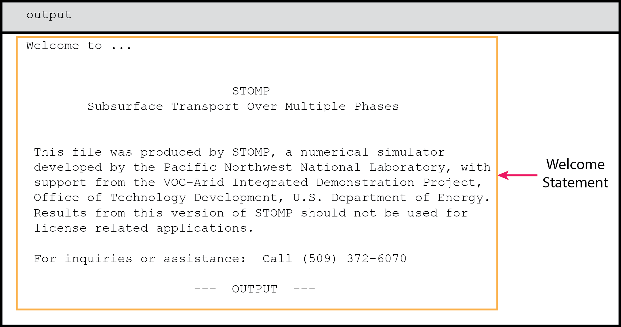
An output file begins with a welcome statement, disclaimer, and banner, which should appear similar to:
Input Record
Following this banner is an input record, which documents the simulation input.
An input record is included on the output file to document the simulation in the event that the input file is inadvertently deleted or becomes separated from the output file. The input record is formatted differently than an input file, but contains all of the information listed in an input file. Optional cards which are not included in the input file are noted in the input record. If the simulator identifies an input error, an error message will appear in the input record at the point the error was noted. Input cards are read by the simulator in a specific order and will appear in the input record in that order. Because input cards can be organized randomly in the input file, the card order on the input record may not match that in the input file.
Reference Node Output
The reference node output record follows the input record.
The reference node output record is a table of simulation data and selected reference node variables, which are printed according to the frequency requested in the Output Control Card with the input item Reference Node Output File Frequency. A table column header is printed to delineate the columns every 10 print records (1). A link to the list of definitions of the header abbreviations for the reference node output are provided for each operational mode on the Output Control Card options page. Each print record will show simulation data and reference node variable data for each reference node requested. Simulation data comprises the time step (2), the reference node number (3), the simulation time (4), the simulation time step (5), and the number of Newton-Raphson iterations required to reach convergence (6). Reference node variable data comprise values of the variables specified in the Output Control Card through the Reference Node Variable inputs (7).
Reference nodes are indexed by node number. The corresponding i,j,k indices are shown for each reference node on the line preceding the column headers. For example, a simulation with reference node 272 at i,j,k indices of 2, 3, and 6, respectively, would have a reference node header line that appeared as (7) in the following graphic.
Column headers for reference node variables are delineated with an abbreviated title and associated units. Units are enclosed in brackets below the variable abbreviation (8). Definitions of the reference node header abbreviations for the output file are given here. A portion of the reference node output record for a horizontal heat pipe problem involving 50 nodes for time steps 70 through 73 appeared as:
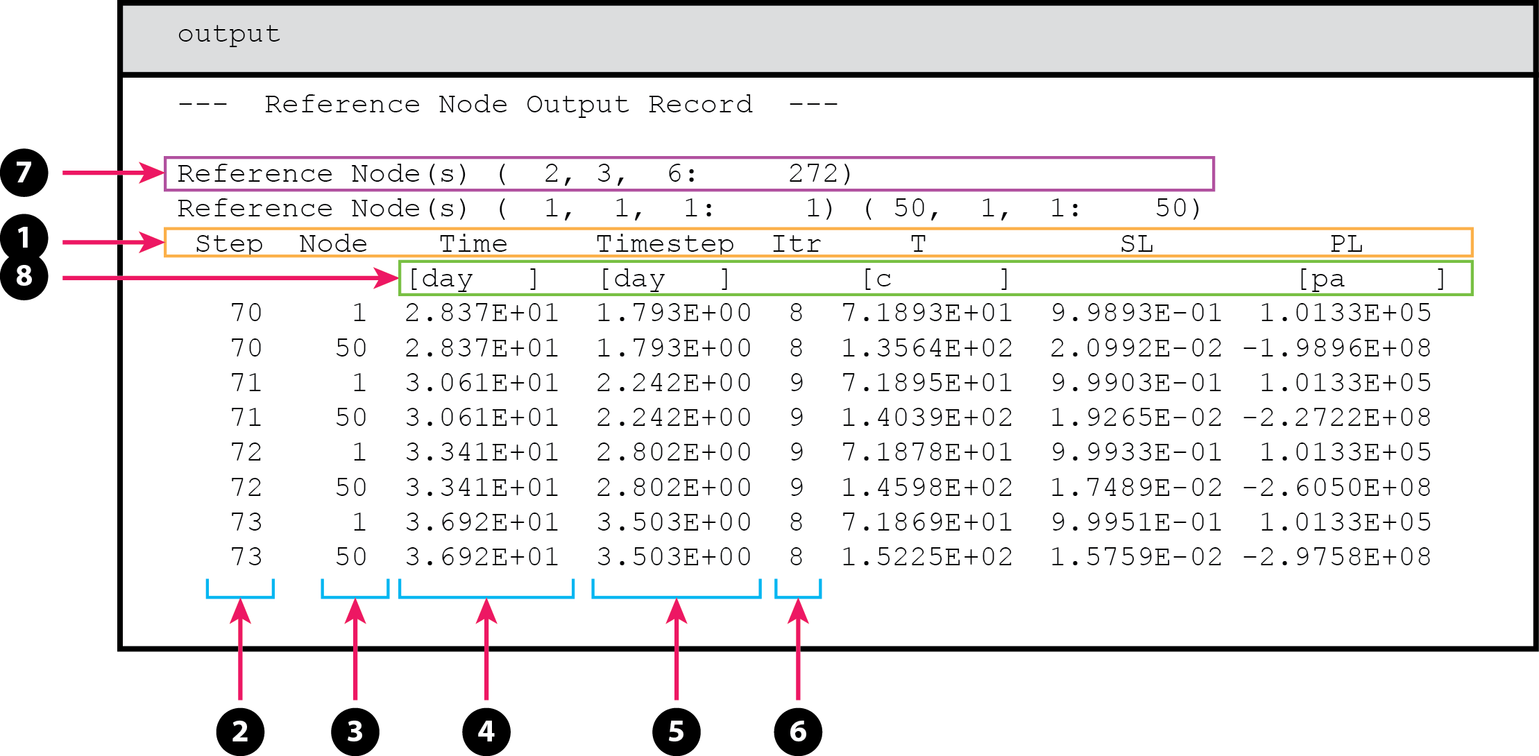
where the reference nodes are nodes 1 and 50, and the reference node variable data includes the temperature, reported in degrees Celsius, the aqueous saturation, and the aqueous pressure, reported in Pascal (absolute) (8).
Convergence failures and subsequent time step reductions are also noted within the reference node output record. Three types of convergence error messages may appear within the output. The first type indicates that the update to a primary variable exceeded the maximum allowable change. An example of this type of convergence error for a horizontal heat pipe problem appeared as:
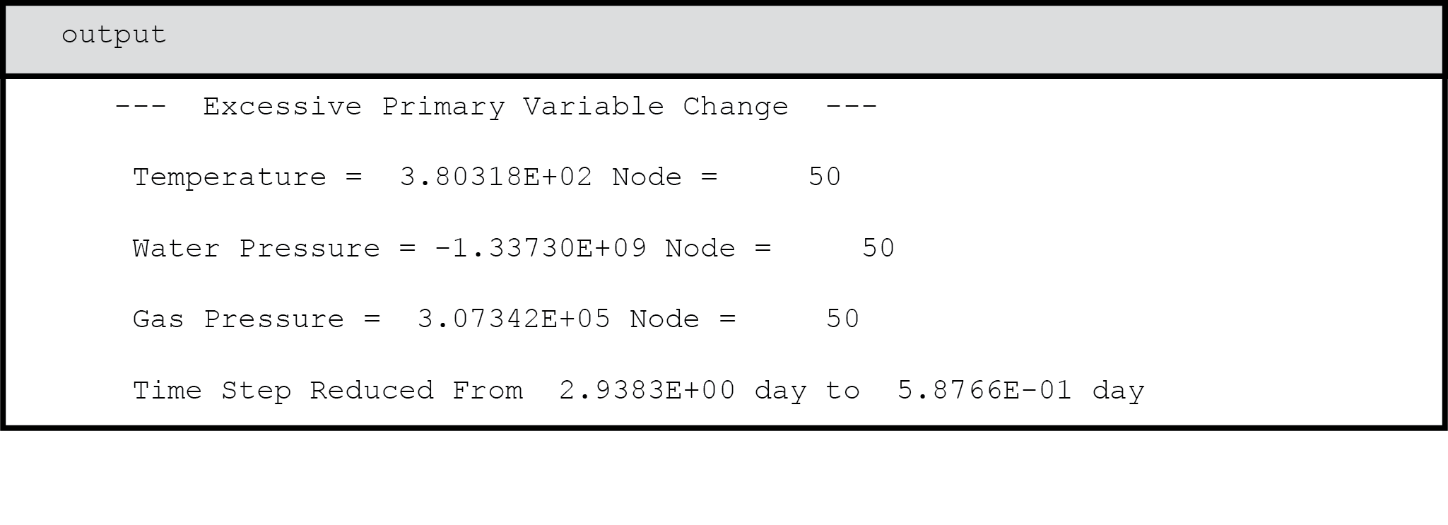 where an excessive change to at least one primary variable was noted at node 50 and the time step was reduced from 2.938 to 0.5877 days and repeated. The second type indicates that a converged solution was not obtained within the maximum number of Newton-Raphson iterations. An example of this type of convergence error for a three-phase volatile infiltration problem appeared as:
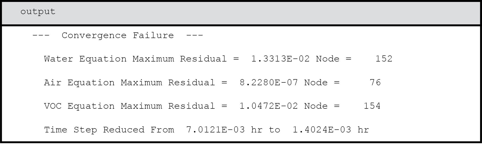
Here the maximum normalized residuals for the water and oil mass conservation equations were noted, which exceeded the convergence criterion. After this convergence failure, the time step was reduced from 0.00701 to 0.00140 hours and repeated.
The third type indicates that the linear system solver has failed to reach a solution. An example of this type of convergence error for a three-phase volatile infiltration problem appeared as
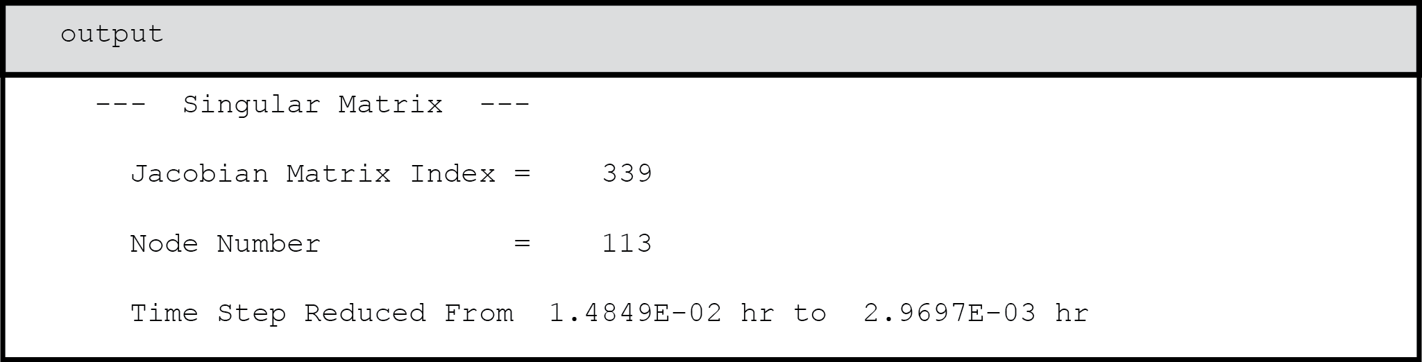
where a zero or nearly zero diagonal was noted for the oil equation at node 113. After this convergence failure, the time step was reduced from 0.0148 to 0.00297 hours and repeated.
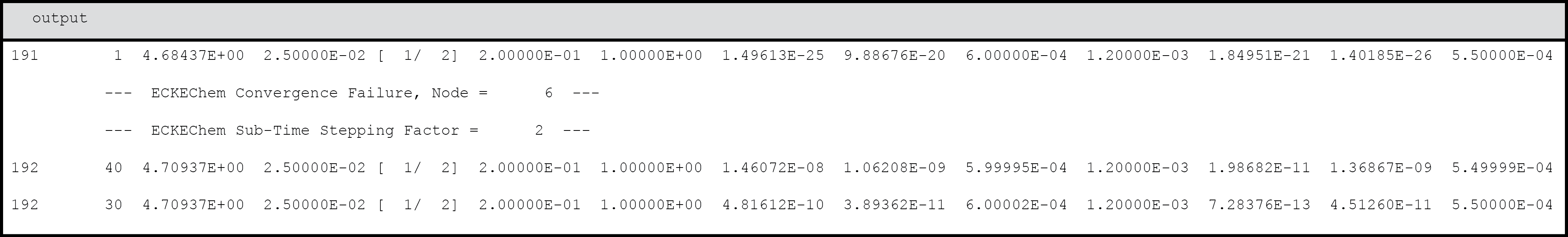
ECKEChem Convergence Errors
Another type of convergence failure can occur when using the ECKEChem (reactive geochemistry) module. The module will report the failure, the node at which the failure occurred, and then create a smaller sub-time step to achieve convergence. A maximum of 16 sub-time steps is attempted before the simulation will abort due to non-convergence.
All of the error messages include additional information that pertains to the specific convergence problem. Convergence errors result in a reduction in the time step with a repeated attempt to solve the system of governing equations. Four successive convergence failures without an intermediate successfully converged time step results in termination of the execution. Output files are concluded with the following closing message.